
Rod End Bearings
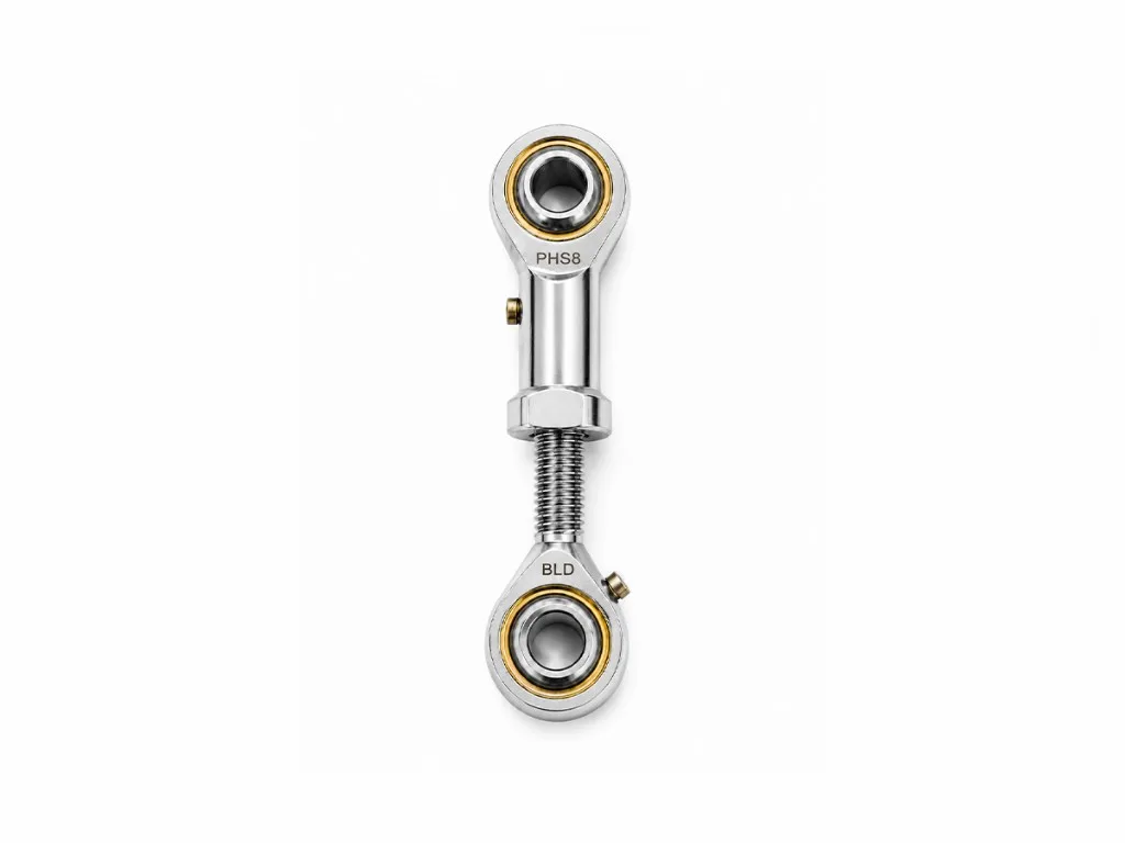
Self-aligning spherical plain inserts with threaded housings for hydraulic cylinders, linkages, and motion systems under oscillating load.
Rod End Bearings
Self-aligning spherical plain inserts with threaded housings for hydraulic cylinders, linkages, and motion systems under oscillating load.
Bearing Overview & Dimensions
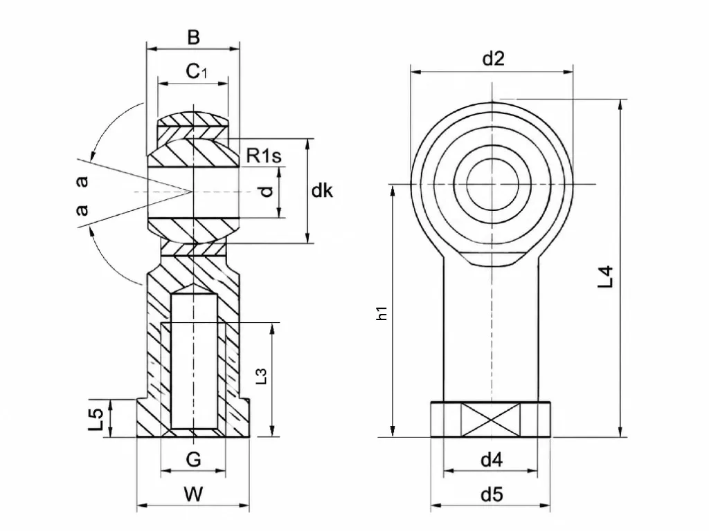
Main Dimensions
- dBore diameter
- B / C1Ball width / head width
- dk / d2Sphere diameter / housing eye OD
- GFemale thread (metric 6H)
- h1 / L4Center height / overall length
Thread & Detail
- L3Thread depth (min)
- L5 / WBase height / width across flats
- d4 / d5Shank / flange diameter
- r1sFillet radius (min)
- αTilt angle
| Bearing No. | Main Dimension (mm) | Load Rating (kN) | Weight (kg) | |||||||||||||||
|---|---|---|---|---|---|---|---|---|---|---|---|---|---|---|---|---|---|---|
| d | B | dk | C1 max | d2 max | G 6H | h1 | L3 min | L4 max | L5 | W | d4 | d5 | r1s min | α≈ | Dynamic | Static | ||
| SI5T/K | 5 | 8 | 11.112 | 6 | 18 | M5×0.8 | 27 | 10 | 36 | 4 | 9 | 9 | 12 | 0.3 | 13° | 5.7 | 6.0 | 0.016 |
| SI6T/K | 6 | 9 | 12.7 | 6.75 | 20 | M6×1 | 30 | 12 | 40 | 5 | 11 | 10 | 13 | 0.3 | 13° | 7.2 | 7.7 | 0.022 |
| SI8T/K | 8 | 12 | 15.88 | 9 | 24 | M8×1.25 | 36 | 16 | 48 | 5 | 14 | 12.5 | 16 | 0.3 | 14° | 11.6 | 12.9 | 0.047 |
| SI10T/K | 10 | 14 | 19.05 | 10.5 | 28 | M10×1.5 | 43 | 20 | 57 | 6.5 | 17 | 15 | 19 | 0.6 | 13° | 14.5 | 18.0 | 0.077 |
| SI10T/K-1 | 10 | 14 | 19.05 | 10.5 | 28 | M10×1.25 | 43 | 20 | 57 | 6.5 | 17 | 15 | 19 | 0.6 | 13° | 14.5 | 18.0 | 0.077 |
| SI12T/K | 12 | 16 | 22.23 | 12 | 32 | M12×1.75 | 50 | 22 | 66 | 6.5 | 19 | 17.5 | 22 | 0.6 | 13° | 17.0 | 24.0 | 0.100 |
| SI12T/K-1 | 12 | 16 | 22.23 | 12 | 32 | M12×1.25 | 50 | 22 | 66 | 6.5 | 19 | 17.5 | 22 | 0.6 | 13° | 17.0 | 24.0 | 0.100 |
| SI14T/K | 14 | 19 | 25.4 | 13.5 | 36 | M14×2 | 57 | 25 | 75 | 8 | 22 | 20 | 25 | 0.6 | 16° | 24.0 | 31.0 | 0.160 |
| SI14T/K-1 | 14 | 19 | 25.4 | 13.5 | 36 | M14×1.5 | 57 | 25 | 75 | 8 | 22 | 20 | 25 | 0.6 | 16° | 24.0 | 31.0 | 0.160 |
| SI16T/K | 16 | 21 | 28.58 | 15 | 42 | M16×2 | 64 | 28 | 85 | 8 | 24 | 22 | 27 | 0.6 | 15° | 28.5 | 39.0 | 0.220 |
| SI16T/K-1 | 16 | 21 | 28.58 | 15 | 42 | M16×1.5 | 64 | 28 | 85 | 8 | 24 | 22 | 27 | 0.6 | 15° | 28.5 | 39.0 | 0.220 |
| SI18T/K | 18 | 23 | 31.75 | 16.5 | 44 | M18×1.5 | 71 | 32 | 93 | 10 | 27 | 25 | 31 | 0.6 | 15° | 42.5 | 47.5 | 0.320 |
| SI20T/K | 20 | 25 | 34.93 | 18 | 50 | M20×1.5 | 77 | 33 | 102 | 10 | 30 | 27.5 | 34 | 0.6 | 14° | 42.5 | 57.0 | 0.420 |
| SI22T/K | 22 | 28 | 38.1 | 20 | 54 | M22×1.5 | 84 | 37 | 111 | 12 | 32 | 30 | 37 | 0.6 | 15° | 57.0 | 68.0 | 0.488 |
| SI25T/K | 25 | 31 | 42.86 | 22 | 60 | M24×2 | 94 | 42 | 124 | 12 | 36 | 33.5 | 42 | 0.6 | 15° | 68.0 | 85.0 | 0.540 |
| SI28T/K | 28 | 35 | 47.63 | 24 | 66 | M27×2 | 103 | 51 | 136 | 14 | 41 | 37 | 46 | 0.6 | 15° | 86.0 | 107.0 | 0.720 |
| SI30T/K | 30 | 37 | 50.8 | 25 | 70 | M30×2 | 110 | 51 | 145 | 15 | 41 | 40 | 50 | 0.6 | 17° | 88.0 | 114.0 | 0.820 |
| SI30T/K-1 | 30 | 37 | 50.8 | 25 | 70 | M27×2 | 110 | 51 | 145 | 15 | 41 | 40 | 50 | 0.6 | 17° | 88.0 | 114.0 | 1.100 |
| SI35T/K | 35 | 43 | 57.1 | 28 | 81 | M36×2 | 125 | 56 | 165.5 | 17 | 50 | 46 | 58 | 0.6 | 16° | — | — | 1.600 |
| SI40T/K | 40 | 49 | 66.6 | 33 | 91 | M42×2 | 142 | 60 | 187.5 | 19 | 55 | 53 | 65 | 1 | 17° | — | — | 2.400 |
| SI50T/K | 50 | 60 | 82.5 | 45 | 117 | M48×2 | 160 | 65 | 218.5 | 23 | 65 | 65 | 75 | 1 | 12° | — | — | 5.000 |
SI…T/K / SA…T/K maintenance-free steel/PTFE fabric contact; NHS / NOS inlaid SF1 (female / male, zinc-plated body); left-hand (L suffix) and stainless (S prefix) on request.
Dimensions d, D, L, and thread size M per catalog. Contact us for left-hand thread, maintenance-free, and stainless variants.
Frequently Asked Questions
OEM supply, options, and lead times for Rod End Bearings.
Need Custom Specifications?
We offer dedicated OEM/ODM customization services to meet your specific engineering requirements. Let our technical team provide the perfect solution.
Contact Technical Sales